Product Category
Electrical
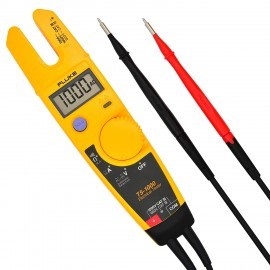
Testers
Purpose-built electrical test instruments designed for installation commissioning, periodic inspection, and everyday circuit verification. From simple socket testers to comprehensive multi-function installation testers, these tools support compliance with wiring regulations and safety standards.
Socket & RCD Testing
Insulation Testing
Loop Impedance
1000VInsulation Test
200GΩMax IR Range
IEC 61557Compliant