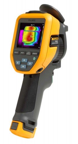
Product Category

Thermal
Imaging Cameras

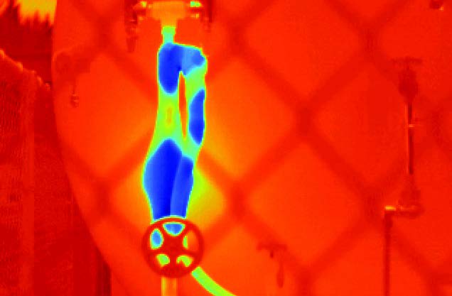
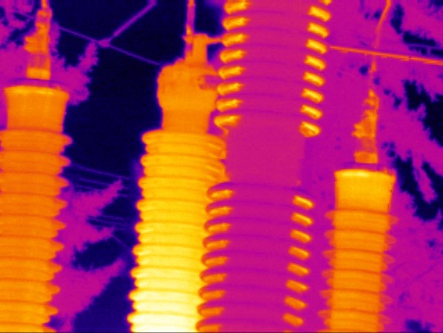
Infrared thermal cameras translate temperature differences into visible images, enabling maintenance professionals to detect anomalies in electrical systems, mechanical equipment, and building structures that are invisible to the naked eye.

Radiometric IR MSX Image Enhancement Thermal Video
Thermal Camera
320×240IR Resolution
±2°CAccuracy
–20 to +1200°CTemp Range

How Thermal Cameras Work

Thermal cameras detect infrared radiation — electromagnetic energy emitted by all objects with a temperature above absolute zero. The camera's detector converts this radiation into a temperature map that is rendered as a visible image using a colour palette. Warmer areas appear in one set of colours (commonly red, orange, and yellow) while cooler areas appear in others (blues and purples).

Unlike visible-light cameras, thermal cameras do not require external illumination. They can image in complete darkness, through smoke, and in conditions where conventional vision would be impaired. This makes them particularly effective for night-time building surveys, fire investigation, and search operations in obscured environments.

Radiometric thermal cameras go further than simply displaying images — they assign a calibrated temperature value to every pixel in the frame. This means an operator can point at any part of the image and read back the temperature at that location. This radiometric data can be stored and analysed with software to generate professional thermographic inspection reports.

Key Imaging Parameters

Detector Resolution

More pixels mean finer spatial detail. Higher resolution allows imaging of smaller targets at greater distances while maintaining accurate temperature readings.

Thermal Sensitivity (NETD)

Noise Equivalent Temperature Difference — measures how small a temperature difference the camera can distinguish. Lower NETD values (e.g., ≤50 mK) reveal subtler anomalies.

Field of View

Wide FOV lenses suit broad area surveys; narrow lenses provide telephoto capability for imaging from safe distances or targeting small components.

MSX Enhancement

Multi-Spectral Dynamic Imaging fuses thermal and visible camera images, embedding visible detail into the thermal image for easier orientation and documentation.

Emissivity Consideration

Accurate temperature measurement requires correct emissivity settings. Shiny metallic surfaces have low emissivity and require adjustment or surface treatment before measurement. Most cameras include adjustable emissivity settings and reference tables.

Technical Specifications

ParameterEntry LevelProfessionalAdvanced
IR Resolution80×60 pixels320×240 pixels640×480 pixels
Thermal Sensitivity (NETD)≤150 mK≤50 mK≤30 mK
Temperature Accuracy±3°C or ±3%±2°C or ±2%±1°C or ±1%
Temperature Range–20°C to +250°C–20°C to +650°C–20°C to +1200°C
Field of View45° × 34°25° × 19°24° × 18° (standard lens)
Visual Camera2 MP5 MP5 MP + autofocus
MSX Image EnhancementYesYes
Laser PointerYesYes
StorageMicroSD (included)MicroSD (included)MicroSD + Cloud sync
Image FormatJPEG + radiometricJPEG + .IS2 radiometricJPEG + .IS3 radiometric
VideoNon-radiometricRadiometric IR videoRadiometric IR video
Battery Life~2.5 hours~4 hours~6 hours (swappable)
IP RatingIP43IP54IP67
ConnectivityUSBWiFi + BluetoothWiFi + Bluetooth + NFC

Applications

Electrical Inspections

Thermal cameras are widely used to survey switchgear, distribution panels, cable connections, and bus bars under load. Loose connections and failing components generate resistive heat that appears as hot spots in the thermal image — often detectable months before the component fails visibly.

  • Switchgear and distribution panel surveys
  • Cable termination and connector inspection
  • Motor control centre diagnostics
  • Transformer and substation surveys

Mechanical Maintenance

Bearing failures, misalignment, and lubrication deficiencies all manifest as temperature anomalies before causing catastrophic failure. Regular thermal surveys of rotating equipment support a predictive maintenance strategy that prevents costly unplanned downtime.

  • Bearing and shaft temperature monitoring
  • Coupling and belt drive alignment checks
  • Gearbox and pump housing surveys
  • Conveyor and drive system condition monitoring

Building Diagnostics

Building inspectors and energy auditors use thermal cameras to locate areas of missing or compressed insulation, air infiltration, moisture ingress, and thermal bridging. These surveys help prioritise remediation work and verify that retrofit insulation has been correctly installed.

  • Insulation voids and compression detection
  • Air leakage and draught identification
  • Moisture and mould risk assessment
  • Underfloor heating system verification

Process Monitoring

Manufacturing and processing facilities use fixed and portable thermal cameras to monitor refractory linings, kiln temperatures, process pipe temperatures, and product quality in continuous operations. Thermal cameras provide non-contact measurement across inaccessible or hazardous areas.

  • Refractory and furnace lining surveys
  • Pipeline and vessel surface temperatures
  • Moulding and forming process quality
  • Food processing temperature verification

Thermographic Inspection Workflow

A structured inspection workflow is essential for producing reliable, repeatable thermographic data. The following steps represent standard practice for professional electrical thermography surveys.

01

Pre-Inspection Planning

Review electrical single-line diagrams and previous inspection records. Identify safety hazards and obtain necessary access permissions and permits. Determine load conditions required for accurate thermal imaging — most electrical standards require equipment to be under at least 40% of rated load during thermal surveys.

02

Equipment Setup

Set correct emissivity values in the camera for the surfaces being inspected. Verify camera calibration status. Select appropriate temperature range and palette for the equipment type. Ensure the camera has reached thermal equilibrium after moving between different temperature environments.

03

Survey and Image Capture

Conduct the survey systematically, working through the facility or equipment list in a consistent order. Capture both thermal and visible-light images of each inspection point. Use the laser pointer or spot tool to identify temperature readings at specific locations. Record environmental conditions including ambient temperature and humidity.

04

Anomaly Assessment

Evaluate identified hot spots against baseline temperatures or manufacturer limits. Temperature rise above ambient and delta-T comparisons between similar equipment are the primary indicators of severity. Reference standards such as NFPA 70B, IEC 60068, or facility-specific criteria to classify anomalies by urgency.

05

Reporting and Follow-Up

Process captured images using analysis software to annotate findings and generate formatted reports. Include thermal and visible images side-by-side, temperature readings, anomaly classification, and recommended corrective actions with priority levels. Schedule follow-up surveys to verify repairs.

Frequently Asked Questions

Most thermographic standards and guidelines — including NFPA 70B and IEC 60068 — recommend that electrical equipment be under a minimum of 40% of rated load during a thermal survey. At lower loads, the resistive heating from loose connections or failing components may not be sufficient to produce detectable temperature anomalies. Ideally, surveys are conducted at or above 80% load to maximise the visibility of potential issues. This is an important consideration when scheduling inspections around production schedules.

Emissivity is a measure of how efficiently a surface emits infrared radiation relative to a perfect emitter (blackbody). It ranges from 0 to 1. Most non-metallic materials (painted surfaces, plastic, rubber, skin, wood) have emissivity values above 0.85 and require minimal correction. Bare metals, especially shiny or polished ones, have low emissivity (copper may be as low as 0.02–0.10 when new) and can produce significantly incorrect temperature readings if the camera is set to the wrong value. For metallic surfaces, either apply high-emissivity tape to the measurement point or use known emissivity correction tables built into most professional thermal cameras.

For general electrical panel surveys where the thermographer is standing 1–2 metres from the equipment, a 320×240 pixel detector provides adequate resolution to identify hot spots on breakers, terminal blocks, and bus connections. For more detailed work — imaging individual fuse clips, small contactors, or equipment viewed at greater distances — a 640×480 detector offers significantly improved target fill and spatial resolution. Entry-level 80×60 detectors are not recommended for professional electrical inspection work as the low resolution makes accurate spot measurements on small components unreliable.

Thermal cameras cannot see through solid, opaque walls or detect objects hidden behind solid surfaces. What they can detect is the thermal signature that a heat source creates on the surface of a wall — for example, a hot water pipe behind drywall may create a warm stripe on the surface, or missing insulation may produce a cold area visible from inside. The camera is measuring surface temperature, not seeing through the material. Detection of subsurface features depends on there being a sufficient temperature gradient between the feature and the surface, and this technique has well-defined limitations that qualified thermographers are trained to understand.

Questions About Thermal Imaging?

Our team can discuss application requirements, resolution selection, and thermographic standards to help you choose the right imaging solution for your inspection programme.